
7.1 General
As mentioned at the introduction, faulting, folding and metamorphism are a consequence of the movement of the plates forming the earth’s crust. In areas of plate divergence, tension causes the ripping of the plates leading to the development of predominantly simple faults, termed normal or extensional, with the broken fragments simply falling due to gravity, and arranging themselves in an array of rifts, with the lower blocks forming “grabens”, and the upper ones “horsts”.
On the other side, along areas of plate convergence, extreme compression fields will cause the development of thrust faulting and intense folding. Both, the diverging as well as the converging zones encompass huge areas, developing topographical features with spectacular characteristics, particularly noticeable on aerial and/or satellite photography, but also as normal scenery.
- In rifting areas, the horsts tend to have an overall flat surface because of the long erosional periods those areas were subjected to prior to the plate rupture. A good example is the highest point of Portugal, Torre, at Serra da Estrela, with an elevation of approximately 2000m and, as figure 125 shows, it has a rather dull flat top.
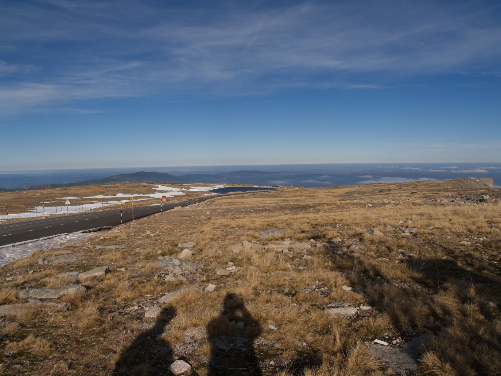
Figure 125 – The distinctly flat top of the highest point in Portugal (Torre, at Serra da Estrela) (view NW)
- On the other hand, in converging boundaries the intense thrust faulting and tight folding give rise to a very rugged topography of sharp peaks and associated entrenched valleys, as for example the Alps (fig. 46).
7.2 Faulting
Faulting takes place when the rocks under stress are brittle. Of the simple faults associated with Diverging Plate Boundaries, I only have the photo of a miniature graben (fig. 127) which, when it has its relevant dimensions is the main form of a rift valley, with the African Rift Valley as a magnificent example.

Figure 127 – Miniature Graben (Furnas, Alentejo, Portugal) (escarpment approximately 2.5 m high).
Of the other simple faults, I only have two photos of rather small, but quite explanatory reverse examples. In figure 128, the proof that it is a reverse fault is that there is a duplication of the dyke within the dyke/fault vertical projection. In other words, the block on the right was pushed up. So, that is the upthrow side.

Figure 128 – Reverse fault/dike (Boula, India).
In figure 129 the dragging of the sediments on the upthrow side makes quite clear which way the movement was.

Figure 129 – Reverse fault with drag of sediments on the up-throw side (Cape Peninsula, South Africa).
All the fault photos shown so far, are from artificial land cuttings that is, they show cross sections, which is the easiest way to visualise a fault. However, this is not the most common view of a fault when doing field work. In fact, with the large ones we only become aware of them when the geology is plotted on a map, and the fault appears as a linear structure offsetting the stratigraphic succession across which it cuts. Figure 129B is an exceptional example because it shows the fault and its displacement on a horizontal land surface and this is only observable because the fault is tiny. As can be seen, the sedimentary beds dip towards the photographer and, to the right of the fault, the bedding plane strike lines are further away. Thus, the right hand side fault block is the downthrow side since it dropped relative to the other one and, as the erosion levelled the ground, the strike lines were displaced towards a higher bedding plane position. As we used to say, the downthrow side moves up-dip.

Figure 129B – Plan view of a fault with the downthrow side on the right hand block (actual fault throw possibly less than 0.5 m) (Praia das Avencas, Parede, Portugal).
Of the thrust faults, which tend to be quite flat, because the movement within converging plate boundaries is mainly parallel to the earth’s surface, the only one I have is not so clear, but it gives the general idea (fig. 130).

Figure 130 – Almost horizontal thrust fault (Odeceixe, Alentejo, Portugal) (escarpment hight, over 15 m).
Other items related to faulting are:
– Slickensided fault plane, defined as the polished and smoothly striated surface resulting from the friction along a fault plane. Figure 131, is an example of a strike-slip fault, because the striations are almost horizontal. Also, the movement of the block on the observer’s side was from right to left, since the sharper angle of the humps tend to be predominantly on the left side.

Figure 131 – Slickensided fault plane (Boula, India) (view hight approximately 3m).
– Fault breccia, defined as the assemblage of angular fragments resulting from the crushing and shattering of rocks during the movement on the fault, is shown in figure 132.

Figure 132 – Fault breccia (Tete Region, Mozambique).
– Mylonite is defined as a compact rock with a streaky or banded structure produced by the extreme granulation and shearing of the rock pulverised during the thrusting. The development of very high pressure and temperature causes partial melting, giving the rock the appearance of a micro-brecciated toffee (fig. 133).

Figure 133 – Fault plane filled with mylonite (Buffelsfontein Mine, Stillfontein, South Africa).
Finally, as mentioned above, faulting takes place under brittle environments. The stress release in such fields tend to develop fault sets that are close to perpendicular to each other and they are termed Conjugate Faults. Again, evidence of such occurrences are far more easy to visualise in a global scale and become very distinct when they are sufficiently strong to control the geomorphology . Once more I make use of Google maps to show a rather impressive example, where the Douro River, in the North of Portugal, at one stage flows on an almost straight line in a SSW direction, to sharply veer to another very straight line, but now in a WNW direction (centre of figure 133B). Those lines are so straight that there can be no doubt that they represent a strong set of conjugate faults.

Figure 133B – Example of geomorphological control by conjugate faults (Douro River, Portugal) (after Google)
Just to finalise faulting, since I have two rather nice photos, I must mention, but only briefly, the most important ones which are the transform and their associated transcurrent faults which are intrinsically related to the tectonic plate movement. Wikipedia defines them as:
- Transform Fault is a plate boundary strike-slip fault where the motion is predominantly horizontal. It ends against another one, or at the end of the plate.
- Transcurrent Fault is closely related to the transform fault, but is far less persistent, terminating without a junction.
I show the transcurrent fault first (fig. 133C) because of the observable impressive corresponding detail. As it can be seen, at the near side of the photo, the sediments have an approximately N-S strike with a gentle eastwards dip. In the mid ground though, over an extent of about 200 m, the strike changes abruptly to almost E-W, with a moderate northerly dip. At the promontory on the background, the strike reverts to N-S. The area where the sediments strike E-W, is surely the fault drag zone and, in my interpretation, the northerly dip indicates a westwards movement of the northern block relative to the southern one, and this also explains the promontory. That is, there was a sinistral movement. I consider this a transcurrent fault, because its extent inland is rather limited.
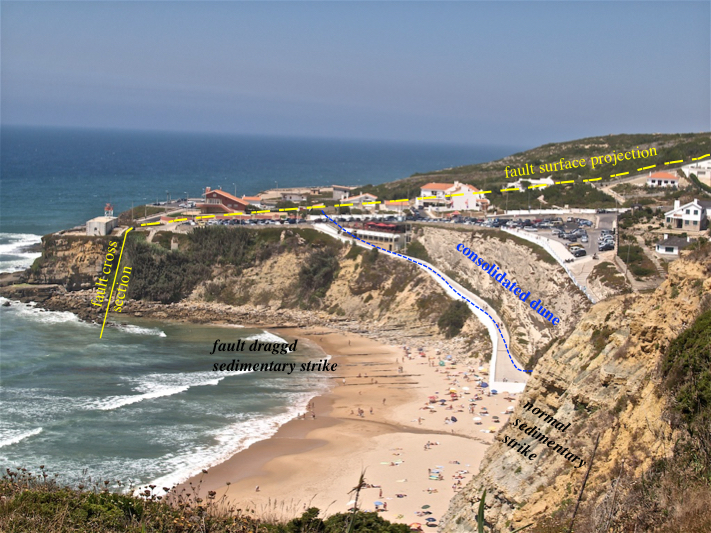
Figure 133C – Costal escarpment, showing a transcurrent fault and the associated dragging of the nearby sediments (view N) (Magoito beach, Portugal)
Going now to the transform fault. Figure 133D shows the large promontory such a fault caused at Nazaré. Again we are dealing with a sinistral movement, since the promontory is on the North side. This time, the fault extends kilometres inland and, westwards, continues towards where the Central Atlantic Ridge was at the time when the ripping occurred. The other consequence of this ripping was the formation of a deep underwater canyon that permits the development of the local huge and famous surfing waves.
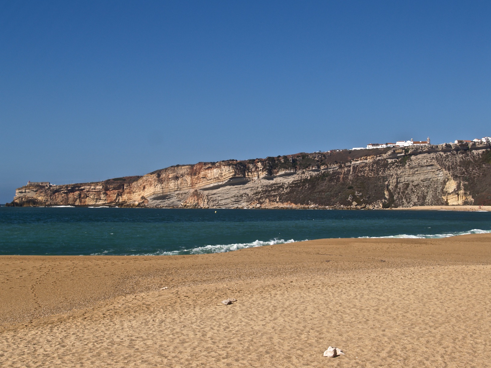
Figure 133D – The large promontory formed by the Nazaré transform fault (view N) (Nazaré, Portugal)
7.3 Folding
Folding takes place when the rocks are sufficiently plastic. That is, it occurs at considerable depths under compressional conditions, which means, a Converging Plates environment. The simplest folds are the syncline, where the fold forms the bottom of a trough, and the anticline, where the fold forms the crest. Figure 134 shows a simple synclinorium with a broad anticline on the left, followed by a broad syncline on the right.

Figure 134 – Simple synclinorium (Northern Cape, South Africa).
In figure 135 we have a small anticline, well delineated because of the thinly bedded sediments on which it occurs.

Figure 135 – Small anticline (about 3 m high) (Cape Folded Belt, South Africa).
In the case of figure 136 the anticline is quite tilted, that is, overturned.

Figure 136 – Overturned anticline (Odeceixe, Alentejo, Portugal).
Both these anticlines are small scale examples of the gigantic folding common in orogenic regions. The first within the Cape Folded Belt in South Africa and the second within the Lower Alentejo Flysh Group in Portugal. Much more complete, but very seldom observable, is the grand view of a regional overturned synclinorium with a dimension of kilometers, also within the Cape Folded Belt (fig. 137).

Figure 137 – Very large overturned synclinorium, Cape Folded Belt, South Africa).
Just to finalize folding, figures 138 and 139 show two examples of chevron folds, which are most aptly named.
Figure 138 – Tight chevron folding, Cabo Sardão, Alentejo, Portugal (view about 3 m).
Figure 139 – Chevron folding, Barberton Mountain Land, South Africa.
7.4 Metamorphism / Metasomatism
Wikipedia defines metamorphism as the change of the minerals and structure of a preexisting rock by extreme heat and pressure, without causing its complete melting into a magma. This is the part of geology I like least and as such the one of which I know even less. Within the subduction zone, solid rocks may be remobilized to the extreme of becoming magma again. In the case of only partial remobilisation, when the initial rocks originate from a continental mass, they will have an acid composition and will be metamorphosed to gneisses. Figure 140 is an example of high level remobilization giving rise to a gneiss, where the white streaks are the remaining evidence of some thin quartz rich sedimentary beds which now give an appearance of flowing.

Figure 140 – Flow folding in gneiss (Okiep, South Africa).
In the case of figure 141, if it was not for the presence of a resistant sedimentary remnant (xenolith), it would not be possible, by the naked eye, to determine if that rock was a granite or a gneiss.

Figure 141 – Resistant sedimentary remnant in gneiss (Okiep, South Africa).
Finally, the rock shown in figure 142, on first impression can very easily be considered a granite conglomerate, but in fact it is a greisen, defined by Wikipedia, as a light coloured rock containing quartz, mica and fluorine rich minerals. It results from the hydrothermal alteration of a granite, during the high gas and water rich cooling stages of emplacement. The fluids are forced into the interstitial spaces, thus giving the rock that conglomeritic appearance. Such a rock is quite common in the Castromil area of Portugal where I prospected for gold. Unfortunately the photographs from there were mislaid so I opted to use this one from Okiep in South Africa.

Figure 142 – Possible greisenised granite (Okiep, South Africa).
At Castomil I was told by a Chilean geologist that those rocks were definitely greisen and in Chile it was always associated with thrust faults in the vicinity of magmatic rocks. That is, identical to the Castromil circumstances.
7.5 Stylolites
Wikipedia defines diagenesis as “the processes that cause changes in a sediment after its deposition, but prior to its final lithification”. One of such processes gives rise to stylolites which again Wikipedia defines as “serrated surfaces from which mineral materials have been removed by pressure dissolution, in a process that decreases the total volume of rock, and the insoluble minerals remain within the stylolites making them visible”. Such structures are very common in limestones but are generally quite difficult to recognise, as for example the one shown in figure 111, just to the left of the pen. However, the one shown in figure 142B is the largest I have ever seen and it is very well highlighted by weathering. That is why I had to show it somewhere.

Figure 142B – Very well developed stylolite structure (Tagus River front, Oeiras, Portugal).
Since diagenesis to a certain extent may be considered the first step towards metamorphism, I opted to show this picture here, rather than under sedimentation, as a post depositional process.