For the majority of cases, rocks are fragmented by erosion and\or weathering and transported elsewhere. Sedimentation is the processes to which these materials termed clasts, are subjected to until they are deposited, and the main mechanisms involved are presented in item 6.1. Other materials termed non-clastic, originate from the chemical decomposition of the original rocks, and will be presented in item 6.2.
6.1 Clastic Sediments
Depending on their size, these fragments are transported either in suspension or, if they are considerably larger and/or heavier, they move by saltation. That is, in a series of short intermittent hops close to the ground. Or, if they are really heavy, they simply roll along the surface. In other words, the depositional environment of these sediments is mainly controlled by the transporting mechanisms they are subject to.
6.1.1 Continental Environments
6.1.1.1 Terrestrial
6.1.1.1.1 Aeolian
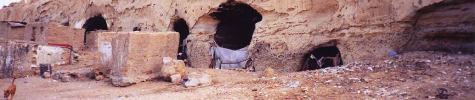
As with erosion, we start with the least energetic agent, air. Aeolian sediments range in the very lower volumetric size in suspension, and a marginally larger dimension in saltation. For wind to be an effective erosion/sedimentation agent, the ground must be unprotected which, under general conditions, means little or no vegetation. Hence the aeolian sedimentary environment is restricted to deserts (fig. 89) and unprotected coast lines (fig. 90).

Figure 89 – Consolidated desert dunes (Namibe, Angola).
Aeolian deposits consist of dunes formed by rather fine grained sand and characteristically have large scale cross-bedding That is, their internal arrangement is constituted by minor layers or laminae inclined to the principal bedding planes, with deposition taking place on the downwind side. At the base, the cross strata sets have a low angle, but upwards the dips increase to over 10º.

Figure 90 – Consolidated coastal dune (Magoito, Portugal).
It is easier to identify cross-bedding in consolidated rocks. I have only seen consolidated desert dunes in the Namibe desert in Angola, but no cross stratification was apparent and, as figure 89 shows, if anything, planar stratification seems to be more likely.
On the other hand, the cross bedding is absolutely distinct at the Magoito consolidated coastal dune. In figure 91 we see a set of moderately steep cross beds at the top, with an almost flat set below, but still quite high up the present dune’s cross section. Since these flat sets tend to form at the base, we must assume that the upper set represents the base of the dune during a later migration stage.

Figure 91 – Cross bedding in a coastal dune (view approximately 4 m high) (Magoito, Portugal)
Large sand deserts are common in areas of low relief and the various types of dunes are a consequence of the local prevailing winds. I have no examples, but the best known ones are:
Dome-shaped dunes, consisting of low, circular, isolated mounds;
Transverse dunes, consisting of almost straight sand ridges at about right angles to the predominant winds;
Longitudinal dunes, also consisting of long sand ridges, but this time oriented along the vector resulting from two converging wind directions;
Barchan dunes, have a crescent shape with the horns extending downwind.
6.1.1.1.2 Glacial
Sedimentation related to glaciation is limited. Its only true representative is the tillite, which is an unstratified, very poorly sorted sediment, composed mainly of fine clasts, but containing disseminated large to very large boulders often striated and faceted. Tillites predominantly cover relatively small areas, other than those related to extensive ice ages. I have no representative photos, but I feel I must mention it here as a matter of completeness. The most common present day examples occur across glacial valleys, have a mound shape, are termed moraines, and form at the site where the glacier melted during a moderately long period. If large enough, these moraines act as dam walls, giving rise to the well known elongated glacial lakes, of which I show a nice sized one in Slovenia (fig 92),

Figure 92 – Glacier lake (Bled, Slovenia).
and a rather small one in Portugal (fig. 93).

Figure 93 – Lagoa Comprida, Serra da Estrela, Portugal.
6.1.1.1.3 Aqueous
6.1.1.1.3.1 Pluvial
1 Ravine Fill
The most basic of these sediments are those deposited on steeply inclined valleys caused by ravinement, where the resulting sediments are a consequence of flash floods, caused by heavy rains, hence the name Pluvial. This environment is characterised by high energy, but with short periods of action. Since these material are transported along very short distances, they show very poor sorting, packing, as well as roundness, and, they tend to occur within relatively long confined channels with very steep sides, for which I present the following examples:
- Figure 94 shows a present day infilling of a ravine, with a very unsorted assemblage of predominately small clasts.
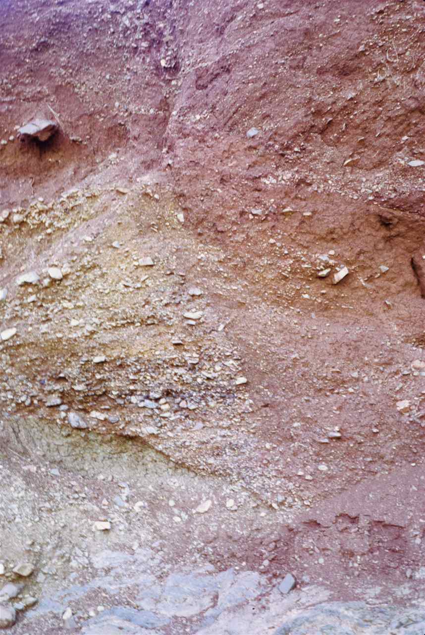
Figure 94 – Present day infill of a ravine (view approximately 2 m high) (Barberton Mountain Land, South Africa).
- Figure 95 shows a close up of the infill at the edge of a ravine cutting across a Jurassic age limestone where again, the clasts are very unsorted and poorly rounded.
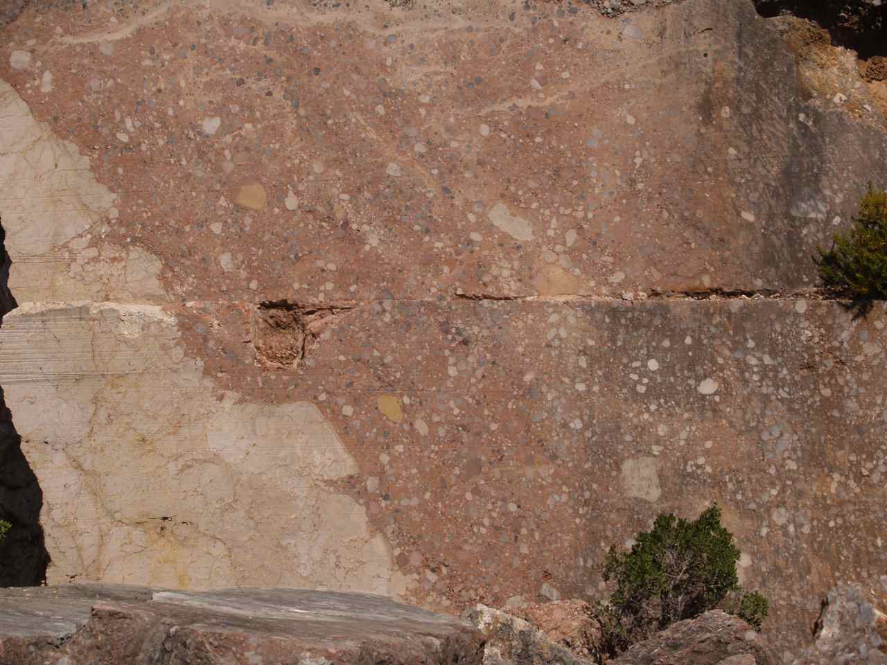
Figure 95 – Infill of a ravine cutting a limestone succession (Arrábida Mountain range, Portugal) – Close up of the edge (quarry face, cutting done by diamond wire) (hight of picture, approximately 2 m)
However, at the bottom of the ravine there is a considerable concentration of the larger and somewhat better rounded clasts (fig. 96).
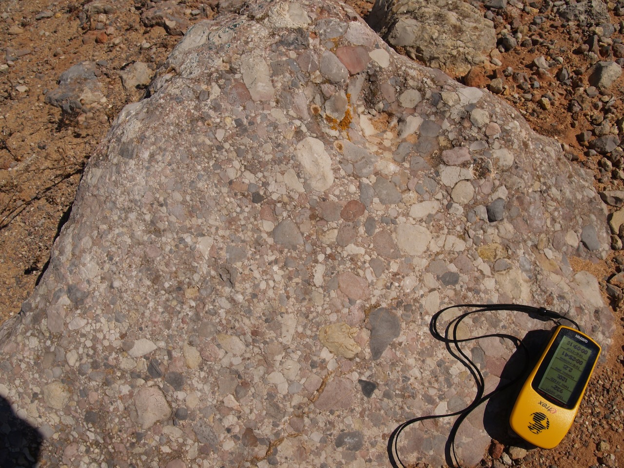
Figure 96 – Close up of conglomerate infill at the base of the ravine shown in figure 95
- Figure 97 shows another example of the infilling of the base of a ravine. Notice the similarity with the infill at the base of the ravine in the limestone of the previous figure, but now I present the gold bearing Ventersdorp Contact Reef (VCR), which lies stratigraphically at the top of the Witwatersrand Supper Group, in South Africa, and where siliciclasts predominate.

Figure 97 – VCR infill at the base of a Ventersdorp age ravine (stope hight, approximately 1.5 m) (East Driefontein Gold Mine S. Africa).
2 Piedmont
Next there is the Piedmont, meaning a deposit at the base of a hill, and its most important sediment type is the alluvial fan which is a low, outspread, relatively conical succession of rather laminar beds comprised by poorly sorted clasts, deposited by water flash flows from narrow mountain valleys upon a flat surface. Each of these stacked sedimentary layers represent individual flush discharge periods caused by heavy rain downpours. When large clasts predominate, the assemblage is termed a debris flow and this was the principal environment during the deposition of the VCR, with figure 98 showing a classical example of two flow periods of large clasts, separated by a shorter flow period of coarse grained sand. Notice too how poorly rounded, packed and sorted the clasts are.
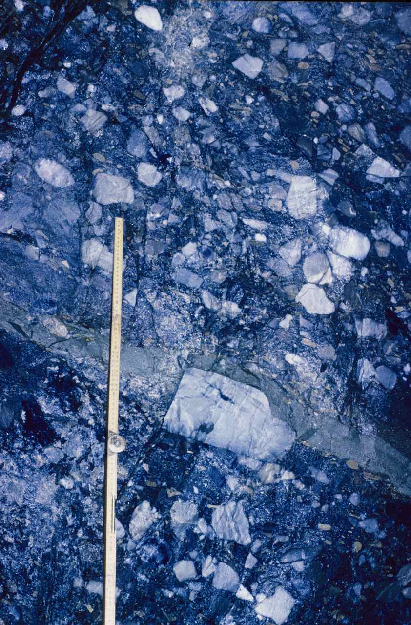
Figure 98 – Debris flow type Ventersdorp Contact Reef (East Driefontein Gold Mine S. Africa).
Often too, the composition of these clasts is very varied (fig. 98B).
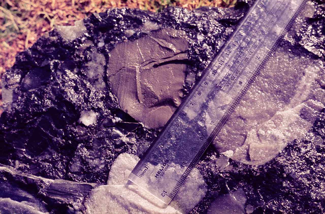
Figure 98B – Example of clast composition variation within the VCR (East Driefontein Gold Mine S. Africa).
6.1.1.1.3.2 Fluvial
1 Braided Streams
Of the different fluvial facies, the first important stage of deposition is perhaps the braided flow regime, where the master stream separates into numerous channels. The energy level is still very high and the deposition of heavy clasts predominates, forming inter-tonguing lenses or small sheets of sediments characterized by cut and fill structures and abrupt changes in particle sizes. A reasonably contemporaneous example can be seen along the Vaal River near Ulco in South Africa, where inter-tonging sand and gravel bars occur, and the gravel sections are locally mined for alluvial diamonds (fig. 99).

Figure 99 – Braided river gravel bar, mined for alluvial diamonds (view approximately 4 m high) (Vaal River, Northern Cape, S. Africa).
Detailed observation of this type of environment shows quite nicely the relationship between adjoining bars of coarser and finer clasts (fig. 99B).

Figure 99B – Close up of inter-fingering grit and sand bars within a braided river sedimentary environment (Lizandro River mouth area, Portugal)
Naturally this alluvial high energy regime is also a sorting mechanism, where the most important factor is mass rather than volume and an obvious example is shown in figure 100 where we have large well rounded quartz pebbles with an SG of 2.6, associated with much smaller, also well rounded, pebbles of pyrite (buck shot), with a significantly higher SG of 5.0. Gold, with an even higher SG of 18, consequently needing much smaller dimensions is also present. In fact, it is seldom visible by the naked eye. In this case though, if my memory does not fail me, at the bottom right hand corner of the picture, those small shiny specks are gold. Returning to figure 99, it is now more easy to understand why the search for diamonds concentrates on the gravel lenses, even though the diamond’s SG is not that high, 3.5.
 (East Driefontein Mine, Carletonville South Africa)")
Figure 100 – Channel type VCR rich in “buckshot” pyrite (sample approximately 20 x 10 cm) (East Driefontein Gold Mine, Carletonville, S. Africa).
2 Meandering
The meandering stage of the river is when high levels of deposition really begin, because this is where the water velocity is considerably reduced. So, we can perhaps assume that this is where normal grading may occur, since that means a continual upwards reduction of clast size within a stratigraphic succession, caused by the diminishing flow strength of the transporting medium. Once again we have a very good text book example from the VCR (fig. 101)

Figure 101 – Graded bedding in VCR (East Driefontein Gold Mine, Carletonville, S. Africa).
Obviously too, deposition will take place preferentially at the inner side of the bends, where the speed is least, thus forming point bars which, with time enhances those bends, as exemplified in figure 102.

Figure 102 – The Catumbela River meanders and its mouth into the Atlantic Ocean (Angola).
During flood periods, the river overflows its banks, dramatically reducing the flow speed thus depositing the very fine silts and muds in suspension, giving rise to rich agricultural soils over the flood plains, also quite distinctly seen. Hence, these marshy areas contain predominantly silts and muds which, during the dry season will desiccate, forming very characteristic mud cracks. Figure 102B, shows a present day example,
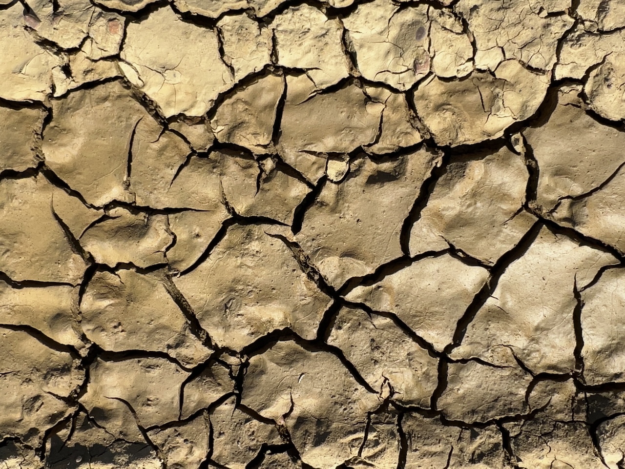
Figure 102B – Present day mud cracks (Praia do Telheiro, Algarve, Portugal).
and figure 102C, shows consolidated mud cracks as well as casts.
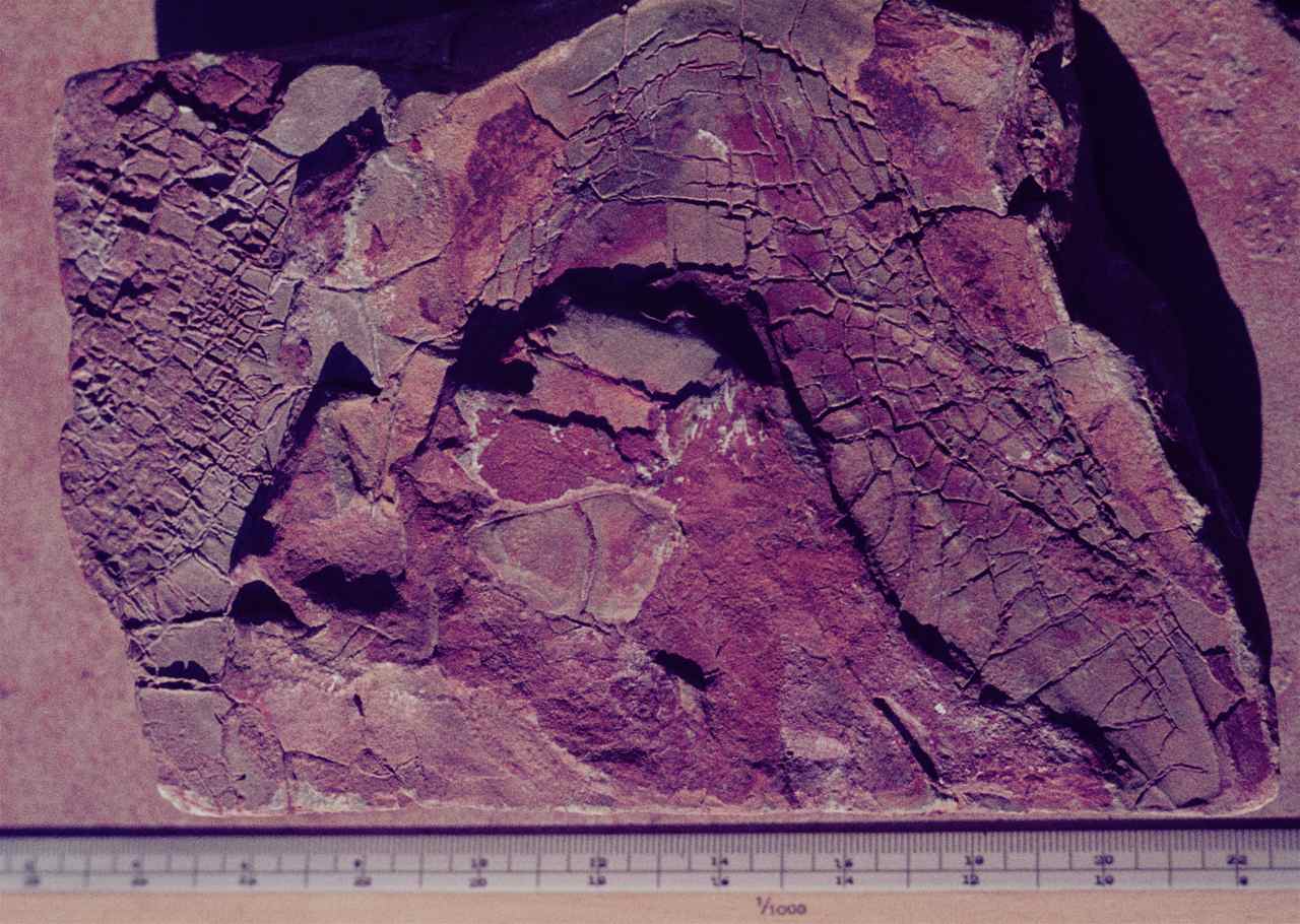
figure 102C – Cast of consolidated mud cracks in mudstone (Transvaal, S. Africa).
A magnificent text book example though, is the one seen in figure 102D,
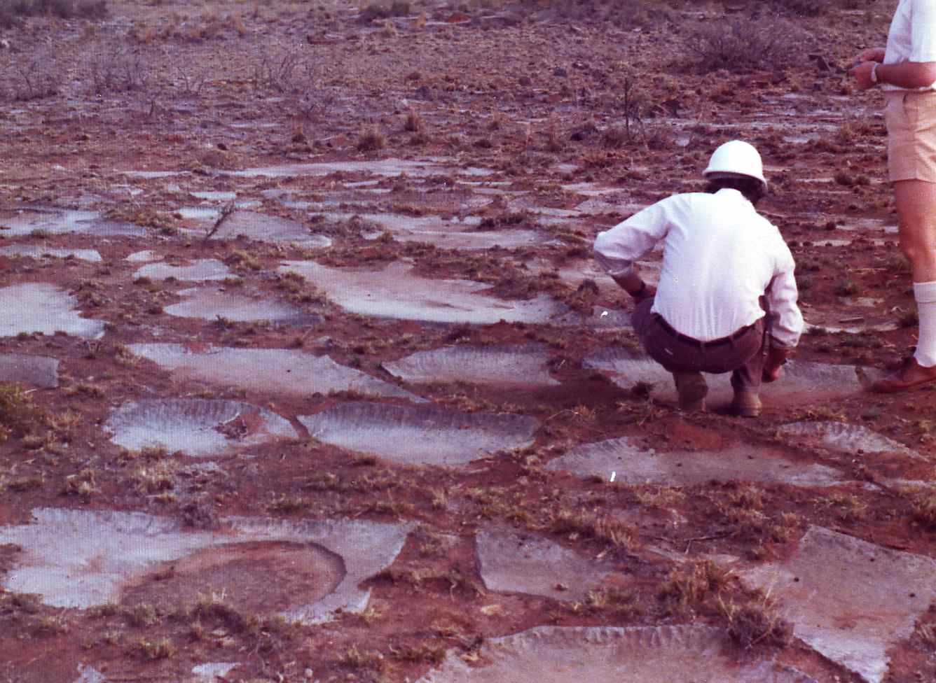
Figure 102D – Preserved mud cracks in limestone (Ulco. S. Africa).
where even the actual curling at the edges of the mud crack slabs was preserved (fig. 102E). As for the slight ripples along the edges and the indentations at the centre of some of the mud plates, I assume they were caused by rain drops, just before there was a new inflow of sediments which covered and thus preserved them.
From the above, it is apparent therefore that mud cracks, seen forming in a present day soil in figure 102B, when covered by new sediments and preserved, are another very useful indicator of a palaeosol, to add to those mentioned under weathering (item 3.2).
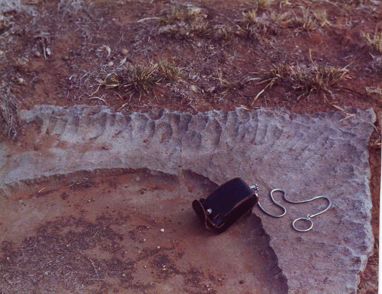
figure 102E – Close view of one of the mud crack plates (Ulco. S. Africa)
Also, within this kind of fertile flood plane environment, we should expect abundant fauna and flora, and the richest portion must surely be the section where the river approaches the estuary or delta, and the river water rich in all sorts of organic matter, contacts the ocean’s salt water. Evidence of this fertility can be seen where there are significant tidal variations, because the mud-flats get exposed (fig. 102F).
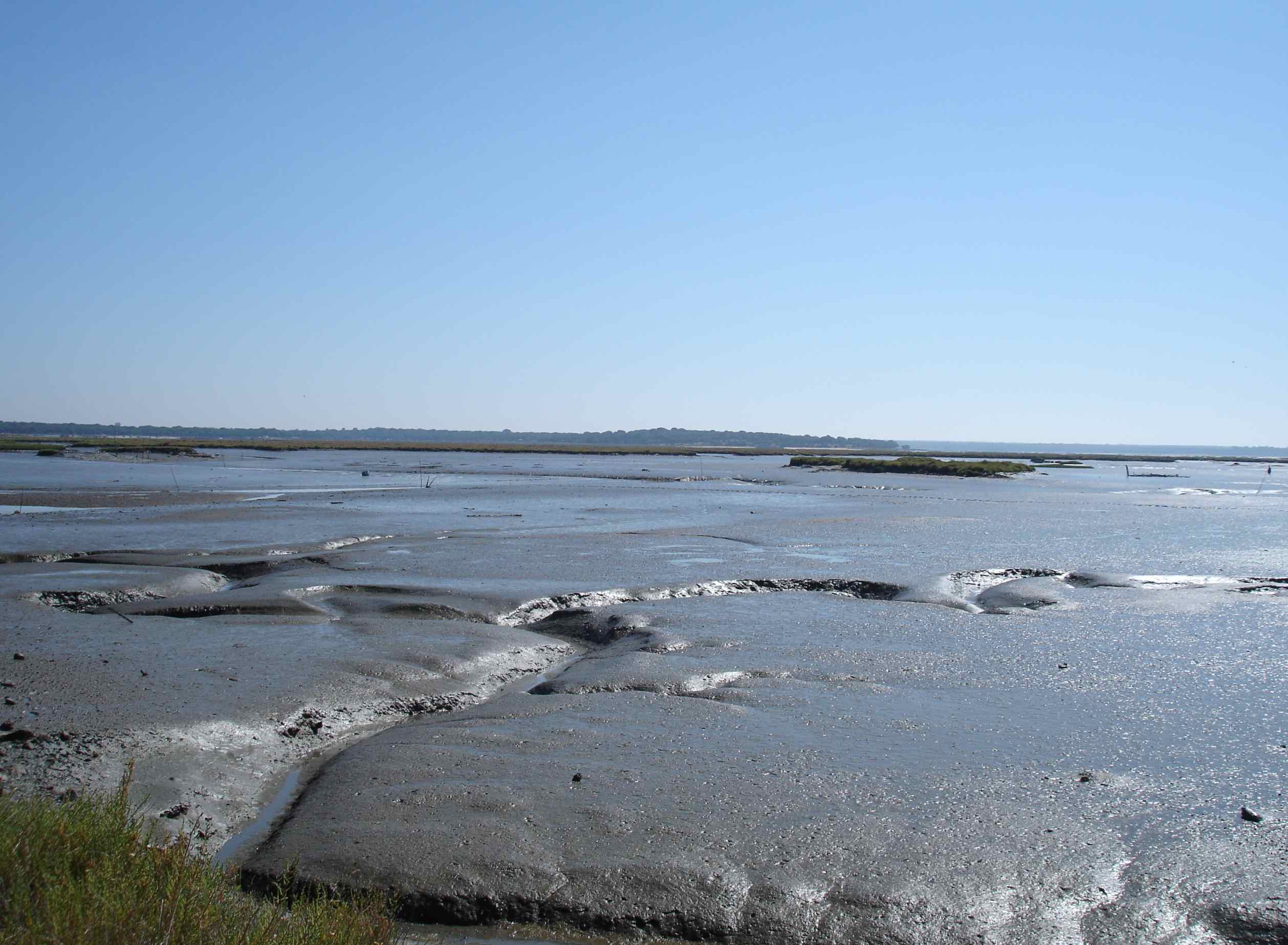
Figure 102F – Present day mud flats rich in burrowing animals (Sado River Estuary, Portugal).
When these present day soils are preserved, forming future palaeosols, the signs of the various types of burrowing animals gives very distinct characteristics to those horizons, termed bioturbated (fig. 102G).
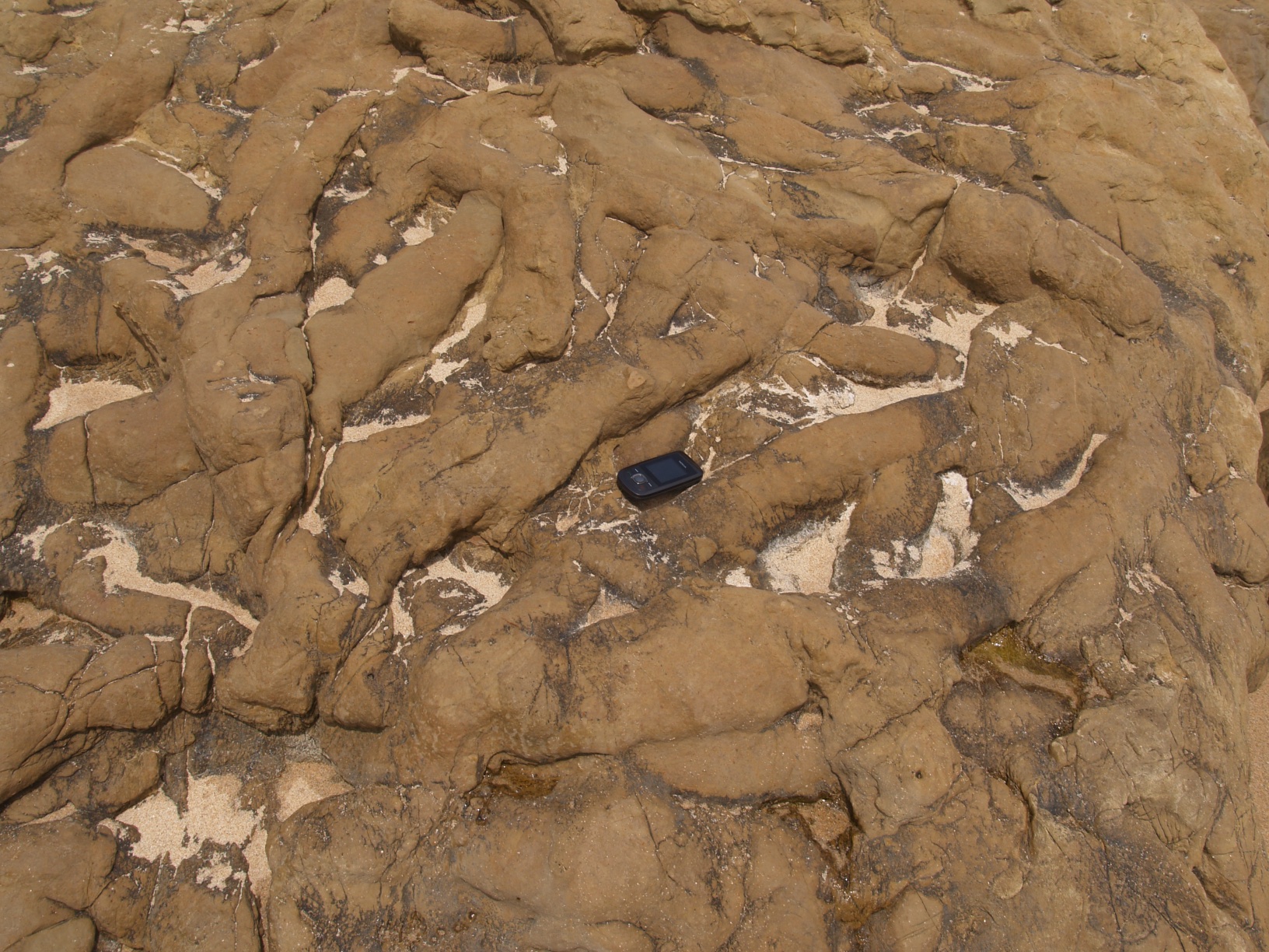
Figure 102G – Preserved burrowing casts in a clayey limestone (bioturbated) (Praia do Guincho, Cascais, Portugal).
What is more, this type of depositional environment has been present for a very long time indeed, as demonstrated by the Ordovician bioturbated horizon shown in figure 102H, which also shows the casts of two large tree trunks.
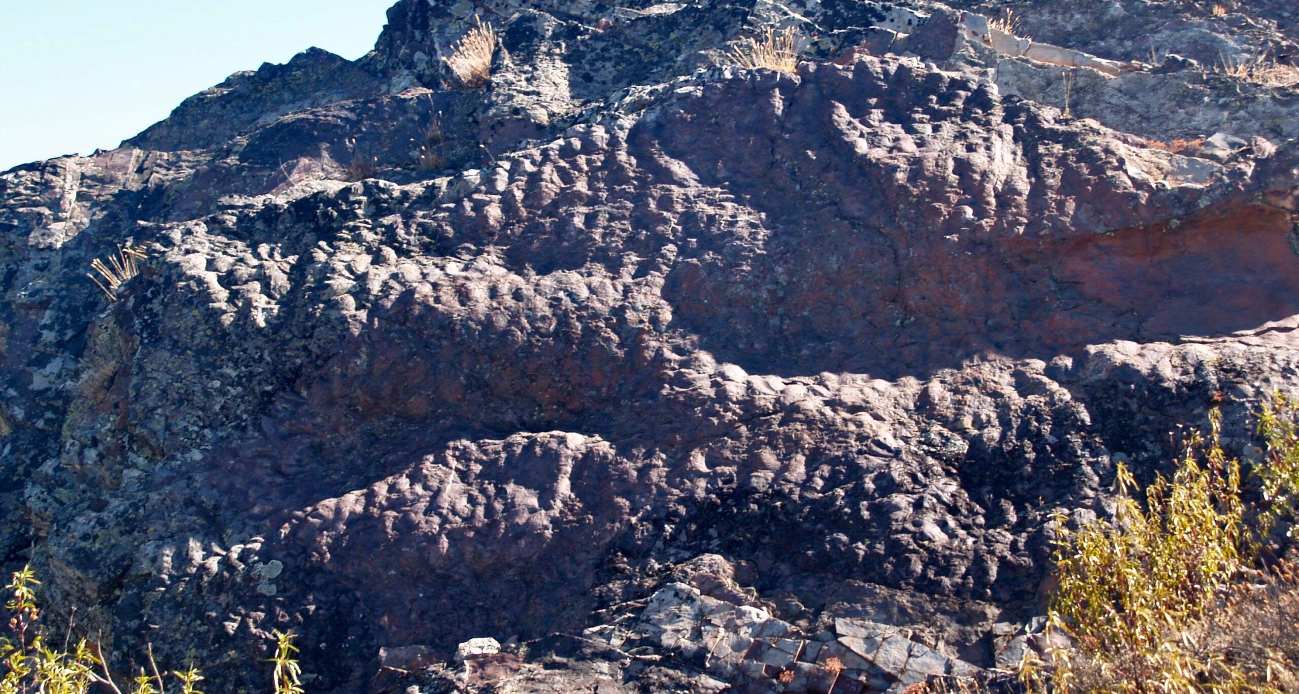
Figure 102H – A magnificent example of bioturbation in an Ordovician mudstone (Penha Garcia, Portugal) (hight of escarpment approx. 2 m)
6.1.2 Transitional Environment
6.1.2.1 Estuary\Delta
I might as well include here the formation of fluvial dunes, because the term dune is no longer restricted to aeolian environments (item 6.1.1.1.1). It has been extended to include sediments from river channels, estuaries and shallow marine environments, where there are relatively strong sustained water flows, because their hydrodynamics are identical to those of the aerial dunes. On the other hand it must be note that the scale of these cross beds is much larger than the classic small scale cross bedding which will be mentioned below, and these two must not be confused because the mechanics of their development are very different.
Perhaps the best example of these fluvial dunes is the one shown in Figure 73B , but for a closer detail view of their scales, I include here figure 102I,
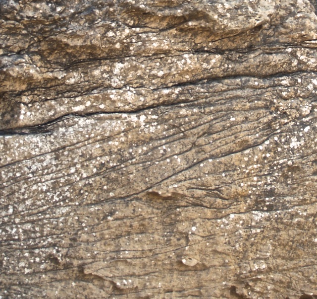
Figure 102I – Crossbedding in sandstone (photo width approximately 15cm) (Azenhas do Mar, Portugal).
and figure 103 showing a rather unique case where the cross-bedding is highlighted by pyrite.
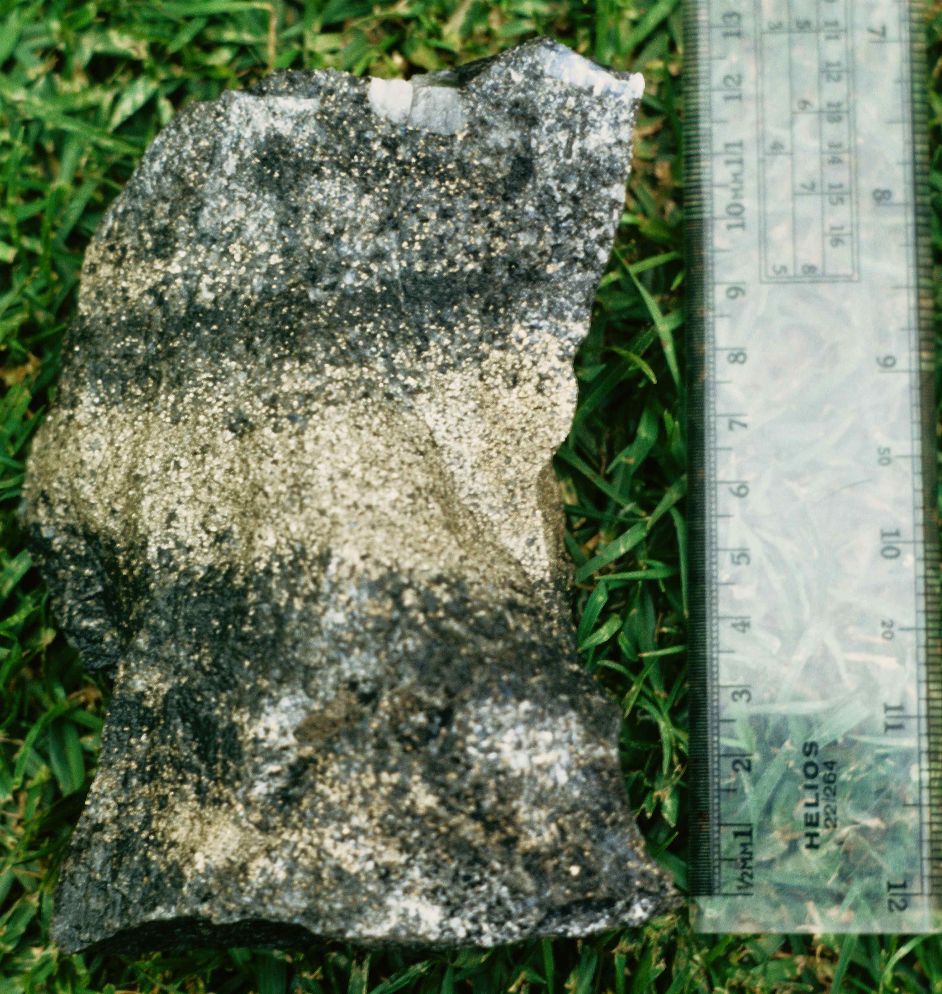
Figure 103 – Cross-bedding enhanced by pyrite in Main Reef internal waste (East Driefontein Mine, Carletonville, S. Africa).
6.1.2.2 Litoral
Under sedimentation, we are interested in prograding coast lines. That is, where sedimentation is taking place, with a consequent shore accretion, and this is also well exemplified by the Catumbela River. It is impressive that even though the river is quite large and carries vast quantities of water, its mouth is actually parallel to the coast, pointing northwards (fig. 104).

Figure 104 – The mouth of the Catumbela River (Angola).
This is caused by the northwards flowing Benguela sea current which is even stronger. Hence, as the river water impacts the ocean current, its speed is dramatically reduced and the bed load particles are deposited, forming a sand barrier termed offshore bar, which progressively grows northwards. With time, this bar widened and the shore line pro-graded, giving rise to sand banks, lagoons and marshes (fig. 105).

Figure 105 – The coast line just N of the river mouth with a pro-grading marshy shore line (Catumbela River, Angola).
Due to an initial coastal reentry, the pro-graded area became quite wide and that is where the town of Lobito developed (fig. 106),

Figure 106 – Wide prograding coast line with the Lobito harbor (Angola).
with the harbor having been formed by the natural extension of the offshore bar created by the Catumbela river sediments (fig. 107).

figure 107 – The sand barrier protecting the Lobito harbour (Angola).
A very conspicuous feature of these arenaceous coastal environments is the development of ripple marks. The example shown in figure 108 is quite striking because the upper bedding plane has current ripples, that is, asymmetric, indicating water flow, suggestive of an environment still under the influence of a river or, with sea currents. On the other hand, the lower one only 5 cm below, has symmetric ripples, indicative of still waters where the ripples are developed by waves caused by the wind. Hence, there is quite a marked facies change, possibly within a relatively short geological time. Significant too is the orientation difference between the two sets of ripples.
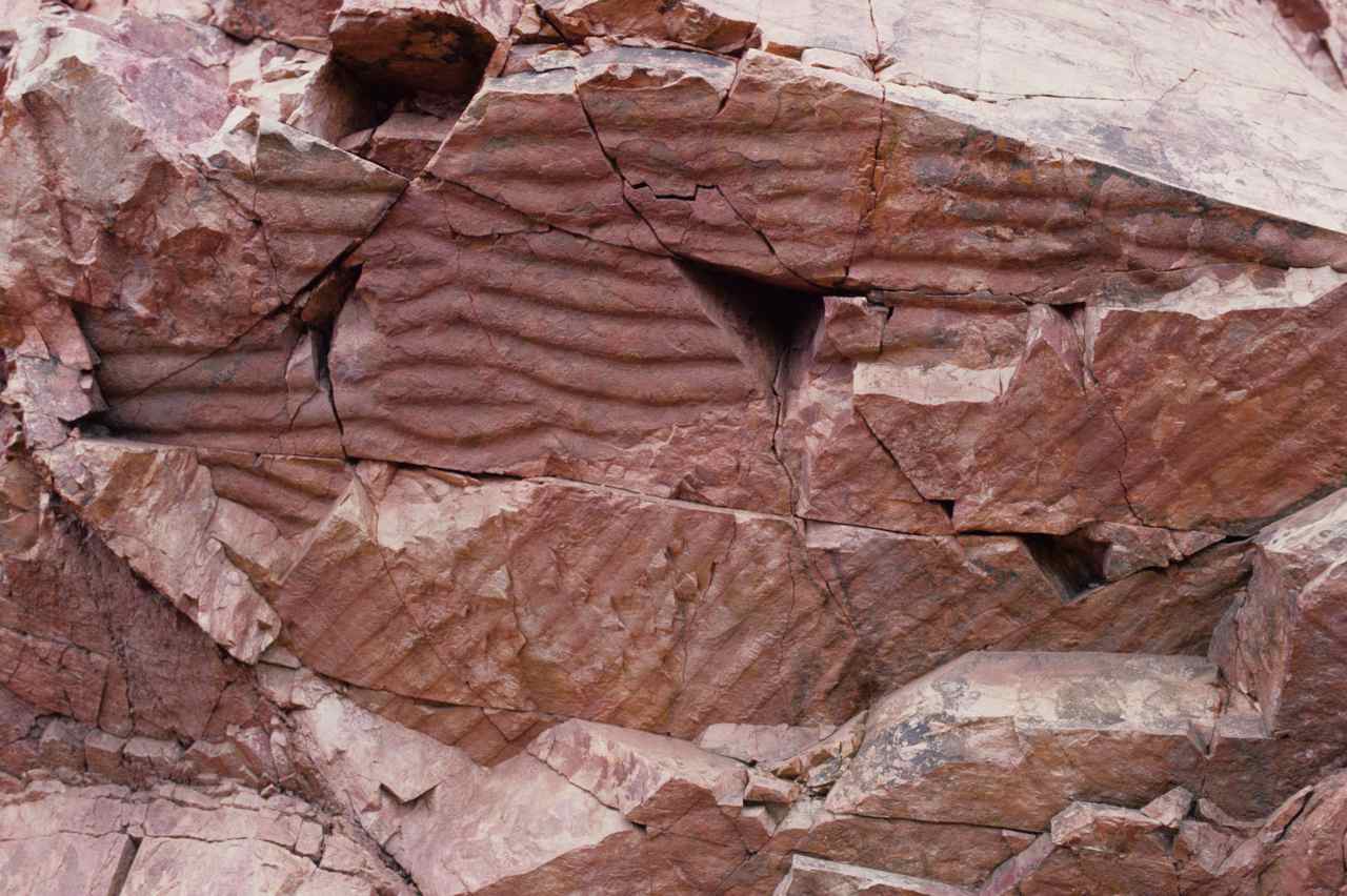
Figure 108 – Ripple marks in quartzite (photo width, approximately 1.5 m) (Ferro Quarry, Pretoria, S. Africa).
Finally, as already mentioned, these beach environments can be very rich in animal life and when there is a limited supply of inorganic clasts, assemblages composed entirely by the accumulation of mollusk shells may occur, giving rise to bioclastic limestone beds (fig. 109).
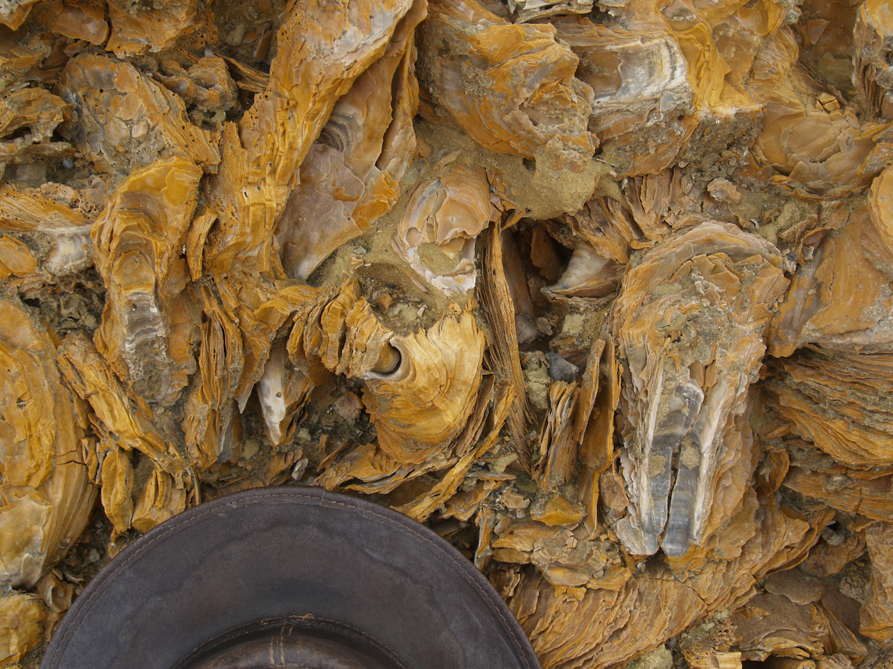
Figure 109 Bioclastic sediment layer (Carcavelos Beach, Portugal).
6.1.3 Marine Environment
6.1.3.1 Shallow Marine (Neritic)
Going away from the coast but still within the continental shelf, in areas with a tropical climate, there is the formation of fossiliferous limestones consisting primarily of coral skeletons originating from the barrier reefs (fig. 110)

Figure 110 — Coral reef limestone (Cabo Raso area, Cascais, Portugal)
6.1.3.2 Continental Slope (Bathyal)
Turbidites are defined by Wikipedia as being formed by turbidity currents that develop at the edge of the continental slope, and consist of a gravity driven turbid mixture of sediments temporarily suspended in water. I know practically nothing about them and have no related photographs, but they must be mentioned, since they are the only true clastic sediments occurring in this environment and form a very significant portion of the sedimentary group of rocks.
6.1.3.3 Pelagic (Abyssal)
Further away from the coast, outside the continental shelf, very little deposition takes place on the sea floor, other than the very slow accumulation of dead plankton and the skeletons of deep water dwellers. Some of the plankton inhabitants have silicious shells and others as well as some algae, produce minute amounts of calcium carbonate. The accumulation of these products on the sea floor often consolidate forming a succession of alternating layers of biogenic limestone and chert. Such a succession is the absolute proof of deposition in a pelagic environment. A very good example of these limestones is the thick succession of the Transvaal Dolomite in South Africa, which contains very abundant inter-layered chert bands (fig. 111). For diamond drilling purposes this is absolute agony, because the very sharp alternation between the relatively soft limestone and the thin but very hard chert bands, destroys the drilling crowns in no time at all.
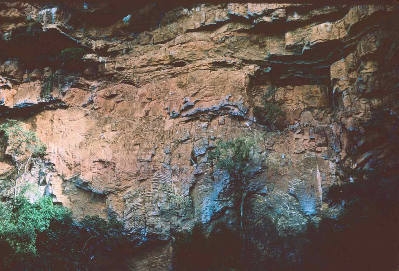
Figure 111 – Column of well marked alternating dolomite and chert (positive relief) (view approximately 10 m high) (Sabie River. S. Africa)
6.2 Non-Clastic Sediments
These are sedimentary rocks formed by the precipitation of chemical compounds carried in solution by the water. Naturally the components of these rocks will be those which are most soluble, like salt, gypsum, chert, calcite and iron.
6.2.1 Chemical Precipitates
6.2.1.1 Limestone
This is the general term for rocks originating from the precipitation of the substances under saturated solutions. Of these, the most abundant by far, are limestones which are constituted almost entirely by calcite. They are generally fine grained and range in colour from almost white, when very pure, to varying shades of gray depending on the quantity of organic matter present.
Travertine is another type chemical precipitate, defined by the glossary of the American Geological Institute as a dense, finely crystalline concretionary limestone formed by the rapid chemical precipitation of calcium carbonate from saturated solutions on to the surfaces over which it flows. A contemporaneous example occurs at Ulco, South Africa (fig. 112). It has a fan shape and is being built by a stream falling over a Northern Cape dolomite ridge. The water flowing over the ridge is saturated with the calcite it dissolved, and than precipitates covering every surface along which the water runs, thus causing the growth of the fan.

Figure 112 – General view of the fan of precipitated calcite from a saturated stream.
A closer view of the continuously growing ridge caused by the accumulation of calcite along the stream is shown in figure 113.

Figure 113 – Close up of the mound created by the stream (Ulco, South Africa)
In fact, one can see growing grass stems being coated by calcite (fig. 114).

Figure 114 – Calcite coating a growing grass stem (Ulco, South Africa).
Diamond drill core cutting through the fan sequence proves that its development was caused by the continuous coating of whatever materials over which the saturated waters flowed (fig. 115).

Figure 115 – Diamond drill core cutting through the Gorokop travertine fan (Ulco, South Africa).
6.2.1.2 Iron
Iron rich solutions within the water table may precipitate at varying depths within a soil profile, forming a hard erosion-resistant layer termed ferricrete, which occurs as a thin sedimentary horizon (fig. 116),
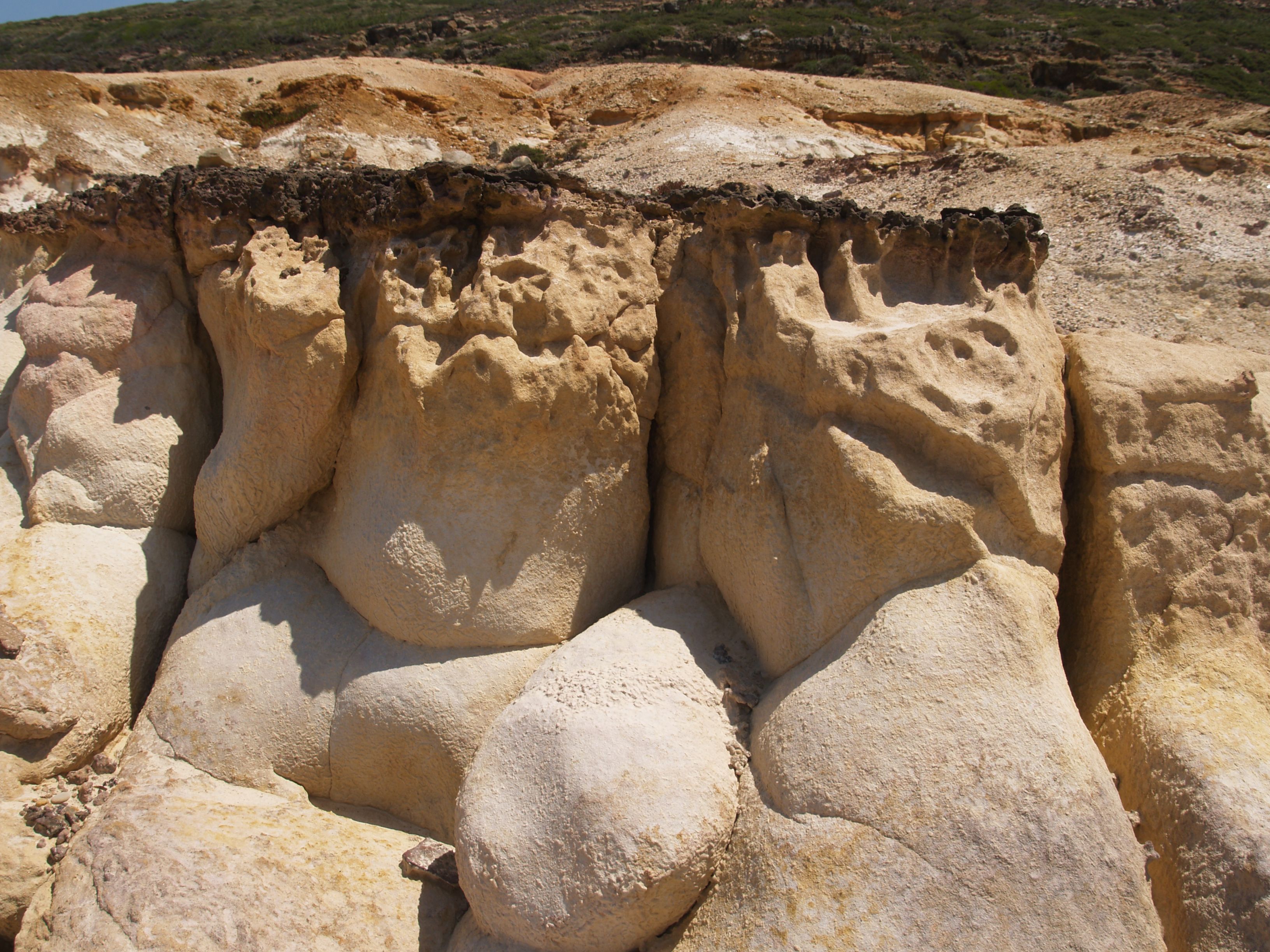
Figure 116 – Thin crust of limonite (about 5 cm) capping a very clean sandstone (vicinity of the Lizandro River mouth, Portugal).
often with a pisolitic texture (fig. 117),
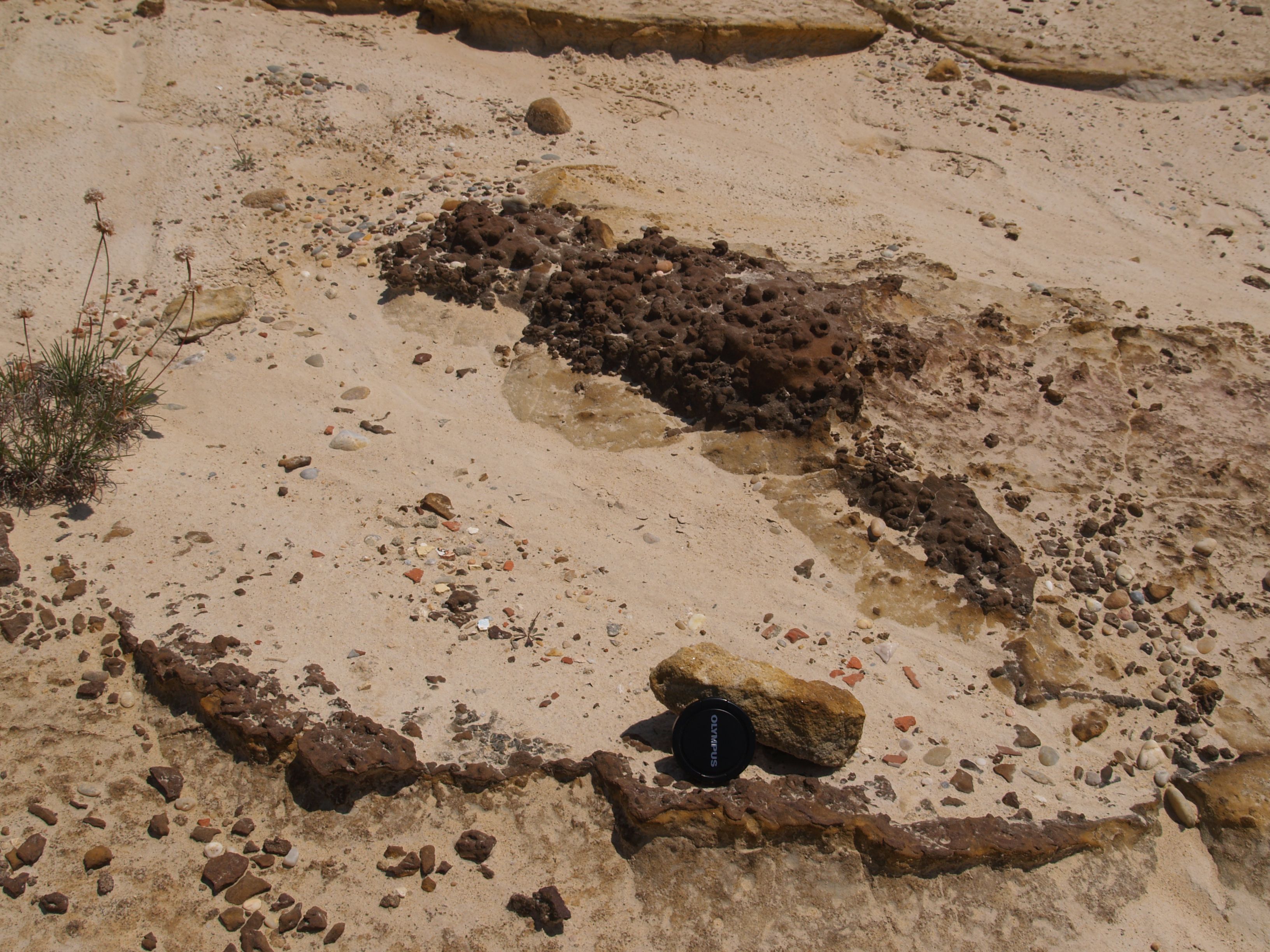
Figure 117 – Close up of limonite crust with a pisolitic texture (Vicinity of the Lizandro River mouth, Portugal).
or it may act as a cement in an originally porous clastic horizon (fig. 118), and it is then often known as a duricrust.
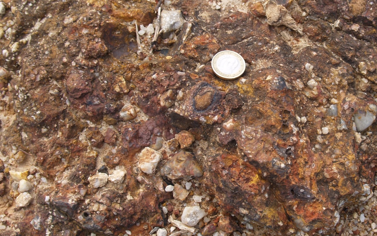
Figure 118 – Ferricrete cementing a very gritty horizon (Cascais, Portugal)
6.2.2 Evaporites
Also defined by the American Geological Institute Glossary, an evaporite is composed primarily by a solution that became concentrated due to the evaporation of its solvent, for example the present day coastal salt pans, of which I show a rather unique example because it occurs within the crater of an extinct volcano in the Sal Island of the Cabo Verde Archipelago. The base of the crater is below sea level and, due to the lavas being very fractured, the sea water seeps into the crater, where it evaporates because of the intense heat caused by the local desert climate, within a totally enclosed area, just like in a cooking pot (fig. 119).
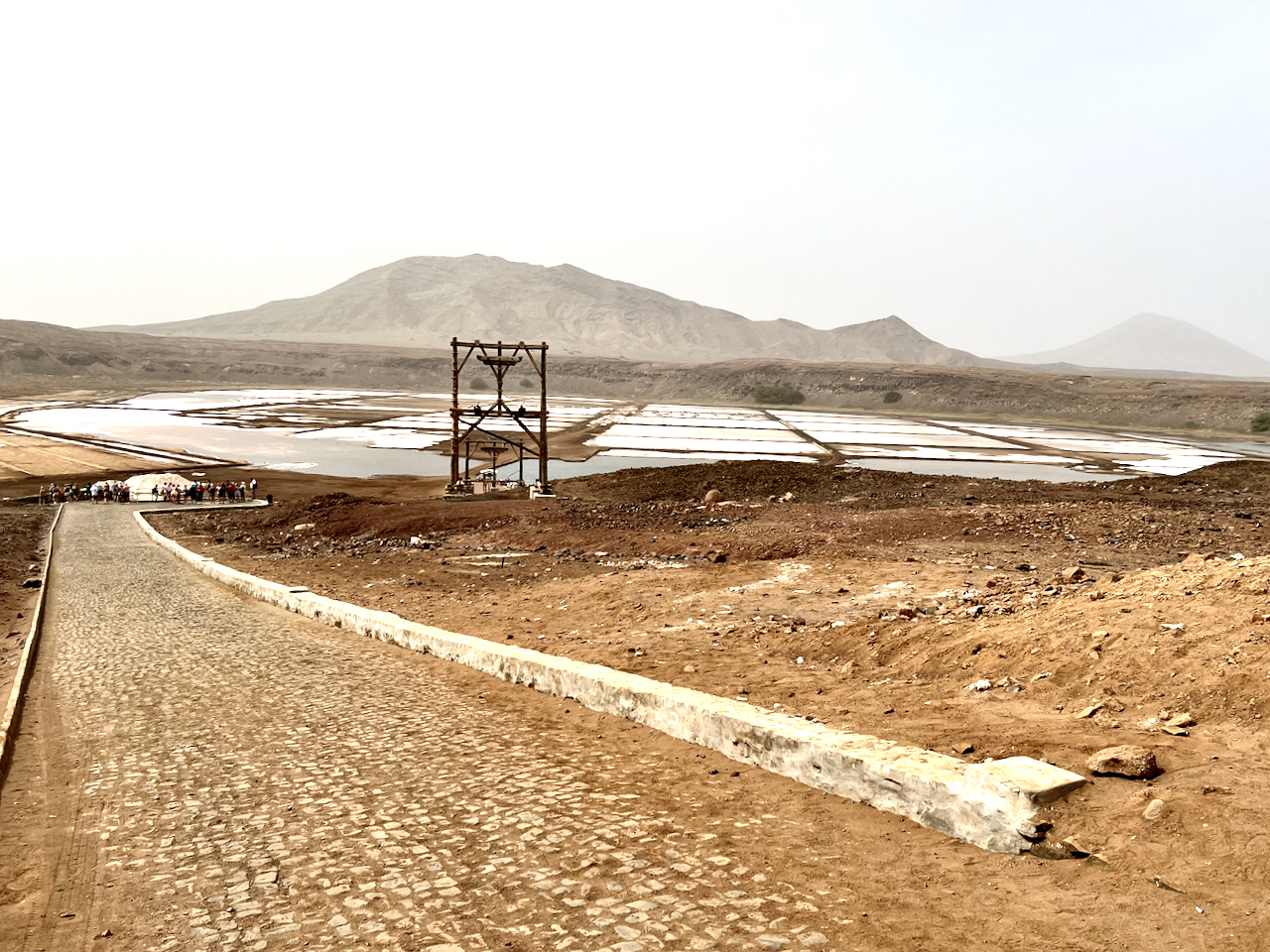
Figure 119 – Natural salt evaporating pan at the base of a volcanic crater (Sal Island, Cabo Verde)
Gypsum evaporites are also quite frequent, but with considerably smaller dimensions, and I saw a relatively large deposit in Angola. Unfortunately I did not have a camera, but I collected a specimen (fig. 120).

Figure 120 – Lovely specimen of fibrous gypsum (Angola)
Also, gypsum as well as calcite may form in desert pools, or from underground water brought to the surface by capillary action. It is under these conditions that the gypsum crystals known as desert roses form (fig. 121).

Figure 121 – Desert rose crystals (Namibia).
6.3 Post Depositional Structures
6.3.1 Fluidisation
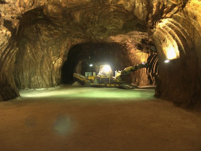
Marine, as well as many continental sediments, tend to be saturated with water. When buried by additional sedimentation, this water is gradually expelled upwards, unless the covering is impermeable. In such cases the trapped water will temporarily behave as a viscous fluid due to the highly increased pressure, and will be expelled at high velocity through the sediments above, whenever cracks develop, often due to earthquakes. One of its consequences is the formation of clastic dykes, as well as diapiric structures when there is a large volume of displaced material. Of the latter, the most well known ones are of salt, mined in many parts of the world, like the one in Loulé, Portugal (fig. 178).
6.3.2 Diagenesis
According to Wikipedia, diagenesis is the sum of post depositional physical, chemical, and biological processes that change loose sediments into sedimentary rock. Here I will refer only to the ones I have come across:
6.3.2.1 Compaction
- In Clastic Sediments – When there is a lateral variation in sediment types, the pressure of the overburden will cause differential compaction, with the finer grains being more compacted, which is particularly noticeable around large nodules (fig. 122).
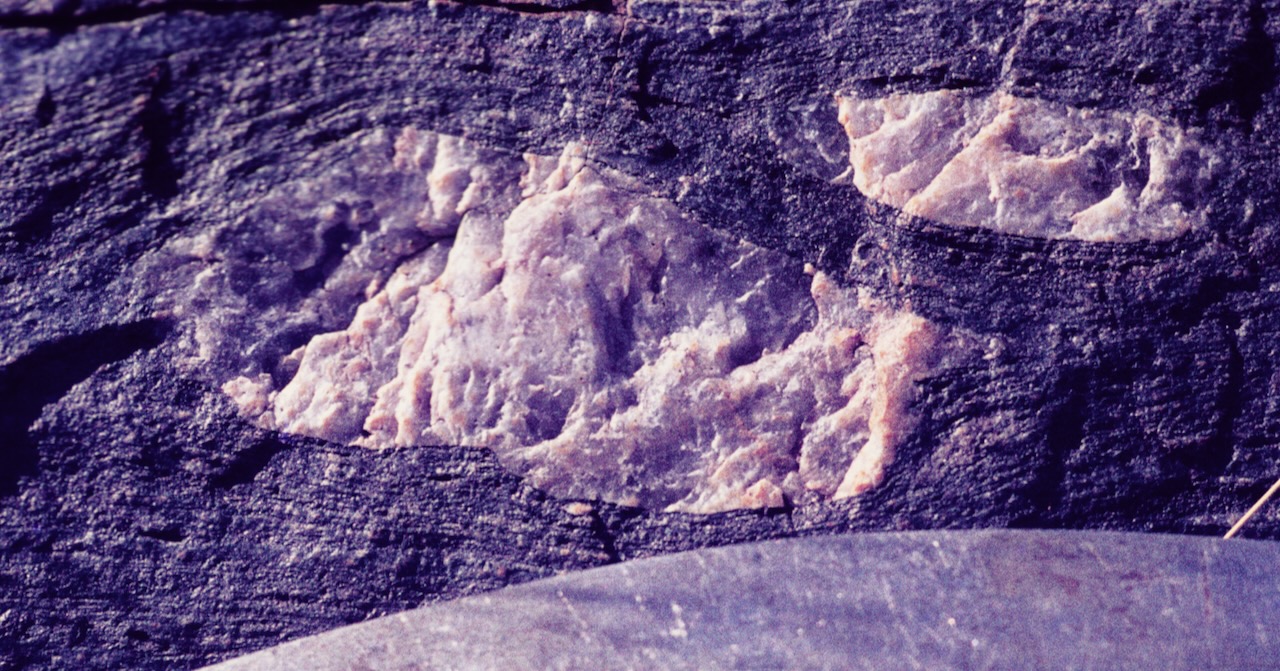
Figure 122 – Distinct differential compaction of the finer grains around the nodules (Pofadder, South Africa).
- Chert Nodules – Chert, in the form of irregular nodules or concentrations occurs in various host sediments, most frequently limestone (fig. 123). They originate from the dissolution of the remains of silicious organisms like sponges, and are formed by the diagenetic silicification of the rock. They are termed secondary chert, to differentiate them from the pelagic or primary chert shown in figure 111. Hence, this chert does not provide any information about the depositional environment, but may be an important indicator of its diagenetic history.
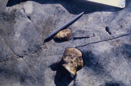
Figure 123 – Close up of silica nodules within a limestone evaporite (Serra do Sicó, Portugal).
- Stylolites – Calcite undergoes pressure dissolution under a few hundred meters of overburden, forming highly irregular millimetric to centimetric solution surfaces that may be enhanced by the concentration of clay, iron oxide or other non soluble impurities. They are termed stylolites and form on a horizontal level when resulting from overburden pressure, but can also be caused by tectonic pressure, in which case they may develop at a high angle to the bedding. Such structures are generally quite difficult to recognise, as for example the one shown in figure 123 just to the left of the pen. However, the one shown in figure 124 is the largest I have ever seen and it is very well highlighted by weathering.
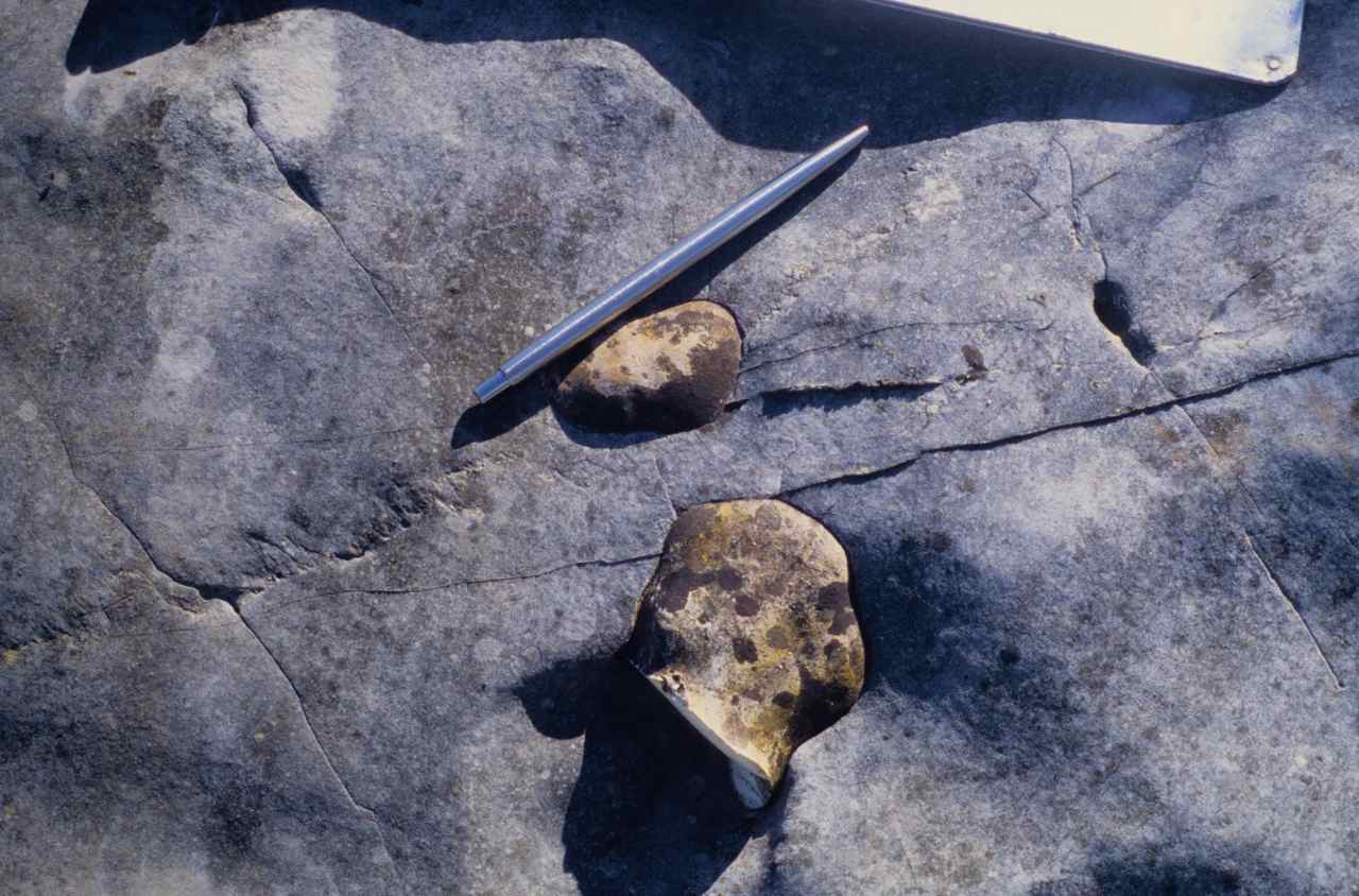
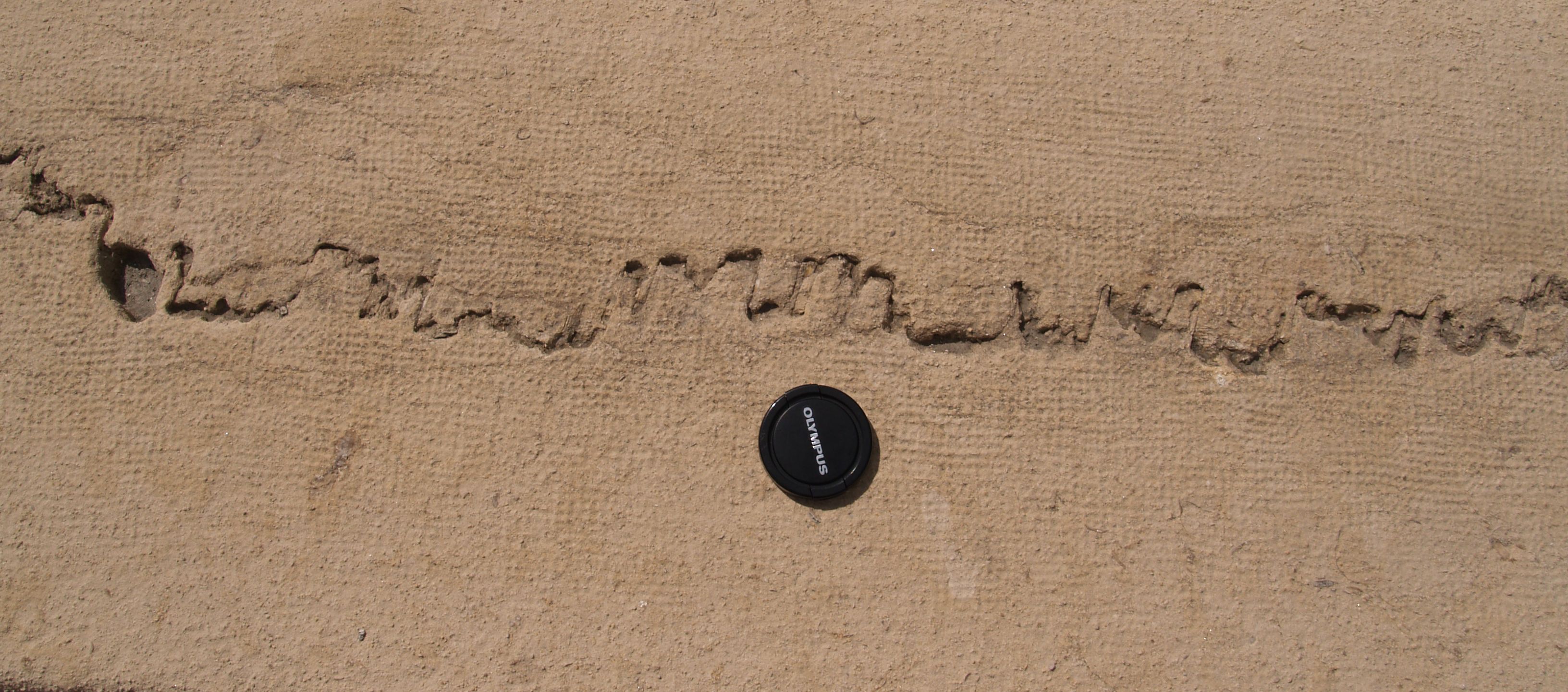
Figure 124 – Very well developed stylolite structure (Oeiras Tagus River front, Portugal).
Sir,
I would hesitate to call the tufa/travertine deposits displayed in fig. 119 and fig. 120 as “evaporites”. As you have noted, these deposits form from surface waters saturated with calcium carbonate. The process of chemical precipitation occurs when carbon dioxide gas is lost due to agitation (like shaking a carbonated beverage). Evaporation of water is not involved in bringing the solution to chemical saturation. Perhaps simply referring to these deposits as chemical precipitates would suffice. In truth, most limestones are not evaporites, rather biological or geochemical precipitates. However, calcrete and carbonate nodules in soils are indeed influenced by evaporation.
Kind regards,
Dr. Doctor
Dear Sir,
Thank you for your welcome comments and I hope that the resulting alterations are satisfactory.
Best regards,
Vitor Pacheco